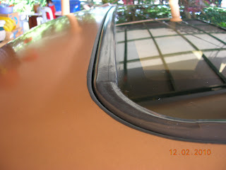
I got this topic up for some time (in 2009), but did not get to publish due to time constraints. It is quite comprehensive, as the sunroof is a unique and electro-mechanical device, having designed to be fitted into a slim space below the chasis top and above the headliner.
As in the pic., with the subroof open, so will the SKY or MOONLIGHT (tips for the young and restless at heart).

The enjoyment however, is quite satisfactory. I spent 3 months rebuilding this sunroof on the Honda Prelude. The mechanisms are basically similar among all the sunroofs, but the materials are not. The glass on the Prelude is heavy duty tempered, with stainless steel frame (photos of the underside later).

Lots of stainless steel was used, compared with newer models, where plastics are subsituted. This part (Part 1) will be more applicable for older sunroofs, or upscale current models that emphasize on quality & durability. Majority of sliding sunroofs utilize a cable or worm screw to actuate the opening and closing of the glass top.

It is VERY IMPORTANT to check and align the gaps around the rubber edge of the sunroof. With big gaps, wind noise, rain water will get into the cabin and spoil all the fun. Think about water dripping into your co-driver's lap ....... or shall I say companion's lap ? Imagine running at 140km/h in the rain. The wind force will sneak in some water, but small amounts is OK, since all sunroofs come with a drip pan (later in photo) that capture stray water drips, but not water sprays occuring at high speeds. As the front is the leading edge, proper alignment of the final stop must be made to ensure a tight fit or water will find its way in on the high speed runs during wet weather. "Whistling" may also occur if there is a gap on this leading edge.

This is a photo of the rear gapping of the sunroof. The drip pan covers from the front to back, which is 2x the length of the glass panel. It cover the total width of the sunroof opening as well. The surface of the chasis roof is slighly convex, with the peak at the centerline of the car. As such, the glass panel will also curve to match the profile. The height of the rubber moulding rise will depend on the design of individual sunroof sealing pattern (edge-to-edge locking pattern).

Looking at the bottom, there is an aesthetic cover that hides all the alignment bolts and mechanisms. The cover may be clipped in position, or screwed, or in combination.

In this example, there is a covered cap for a screw.

Removing the cover reveals a philips screw.

At the rear of the glass panel, when the cover is removed, it reveals two mounting nuts. These nuts enables glass panel height and sideways centering adjustments. Height adjustment is done by looking at the protrusion at or above the chasis roof. Certain feel for "tightness" is required, to ensure a good seal between the rubber moulding and the chasis roof. Glass panel centering is done when all the nuts are in place but loosened, and with sufficient degree of freedom, and the hinges at its natural upright position.

This is the front portion of the glass panel. It also enables both height and centering adjustments. Notice the shims above the bolt plate. A more detailed photo is below.
The shims above the bolting plate enables a fine alignment of the final resting height of the glass panel when it comes to a full stop (at closed position).

Looking from the top with the sunroof open, a rail mounting nut is visible. Since there is a certain degree of flexibility in the centering mechanism of the (usually spring loaded), adjustment of the rail mountings is not required. If the hinges cannot be set 90 degrees upright in the 3rd previous illlustration, adjustments on the rail mountings may be necessary. As mentioned before, the sunroof water drip pan is painted with special anti-rust yellow paint. The glass panel rail mountings are mounted on the water drip pan. Therefore, any adjustments to the rail mountings must be done after removing the water drip pan from the car (aka BIG JOB). Unless the car has been in an accident, rail mounting adjustments are not necessary as expained in the beginning of this paragraph.

The back stop is usually located at the rear of the final stop position of the glass panel. Note the long rectangular protective plastic cover and the ramp at the picture left bottom.
Removing the trim reveals the adjustments for the rear end stop bump. As this is a sliding sunroof, the rear has to come down first before retracted into the cavity below the chasis roof. This stop determines the moment of upside movement in the final stop position (closed
position).
A more detailed view. Moving the stop to the left will raise the rear glass panel earlier and higher. Moving to the right will lower the final elevation of the glass panel rear end on the final stop position.

Pictured is the sunroof panel in opening (or closing ), or in retraction to the underside of the chasis roof. The stopper as described earlier, will determine the final stop height of the rear glass panel at the respective sides (driver / passenger sides).
Post Notes
What is not picture in this illustrations is the sunroof motor, which is hidden above the headliner. It is basically a DC motor, but with friction clutch. It will only be accessible after removing the entire headliner. Unfortunately, when rebuilding it, I did not capture the photos. Maybe sometime in the future, or is there is anyone willing to sponsor the project ?


No comments:
Post a Comment